IoT 6 Channel Switch Module 5V Arduino Compatible
ARD2-2009

$34.95
| QTY | Price |
|---|---|
| 1 | $34.95 |
Description
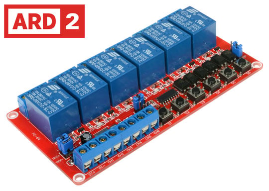
This is a 5V 6-Channel Switch Module capable of controlling various lighting, appliances, and other equipment with higher current. It can be controlled by a Arduino, Raspberry Pi or directly by a microcontroller (8051, AVR, PIC, DSP, ARM, MSP430, TTL logic).
Each channel has an LED indicating whether it is on or off. The board features three operation modes: self-locking, interlocking and trigger. [Jumper B]
Self-locking trigger once, the relay turns on, and then trigger again, the relay turns off. Each channel is independent and will not influence each other. Can be triggered by high level or low level [optional, Jumper C], and can simultaneously control 6 channels.
Trigger mode is trigger on: relay on; trigger off: relay off. Can be triggered by high level or low level [optional, Jumper C].
Interlocking is a typical application of a fan speed switch, when S1 or CH1 is triggered relay 1 latches on, then when S2 or CH2 is triggered relay 1 turns off and relay 2 latches on. Interlock Mode can only have one relay connected at a time. Can be triggered by high level or low level [optional, Jumper C].
Notes
- Unit does not have safety approval in Australia for switching 230VAC mains
- If using external trigger, you must unplug the jumpers [Jumper A]
- If using 12V external trigger, you need a 5.1–6.8K resistor connected in series
- If using a 24V voltage trigger, you need a 15–22K resistor
WARNING: Mishandling or incorrect or improper use of relays could result in serious
personal injury or DEATH, possible physical damage of the product, faulty operation or
create serious/dangerous hazards.
Please make sure that you read and understand how your relay/relay module board works, the voltage and current it is rated for, and the risks involved in your project BEFORE you even attempt to start putting it together. Seek professional and qualified assistance BEFORE you undertake ANY high power projects. Do your research and seek advice BEFORE undertaking a project using a relay. Please check your connections and test them BEFORE turning the power on.
Wiltronics accepts no responsibility for your project, or the risk/damage/fire/shock/injury/death/loss that it causes.
Please note: It is illegal in some countries to wire up a high power project without an electrician. Please check your country's rules/laws/regulations before you undertake your project. If you have any doubts - don't do it.
Test Code for Arduino
void setup(){

pinMode(7,OUTPUT);

}
void loop(){

digitalWrite(7,LOW);

delay(10000);

digitalWrite(7,HIGH);

delay(10000);

}
Specifications
Voltage
5V
Rated Load
DC: 28~30V/10A
Rated Continuous Current
5A
Max. Switch Voltage
30VDC
Board Colour
Red
Material
PCB
Signal Type
5V High or Low [Set by Jumper C]
Dimensions
Length (mm)
110
Width (mm)
57
Height (mm)
18
You Might Also Like
All prices are in Australian Dollars and include GST. GST will be removed from your order if you are ordering from outside Australia.
Products may differ from pictured.
All trademarks and trade names are the properties of their respective owners. Wiltronics disclaims any proprietary interest in trademarks and trade names other than its own.


