The Basics: Breadboards in Electronics Explained
April 6, 2022
Here, we introduce to you the bread and butter of DIY electronics — breadboards.
With a variety of development boards to use out there, there is a lot you can do without a breadboard. But if you are setting up small circuits or need a place for peripheral components, it is a great tool to have.
Many electronics projects, particularly circuits, use breadboards. But what are these pieces, and why are they essential in building circuits?
In this post, you will learn what breadboards are, why they are called breadboards, and how to use them.
What Are Breadboards?
A breadboard is a rectangular plastic board featuring tiny holes. These holes allow circuit components like ICs and resistors to be inserted.
This device is ideal for building and testing circuits before finalising circuit design. It is great for beginners to get acquainted with circuits without the need for soldering. Even seasoned tinkerers use them as starting points for large-scale projects.
They come in various sizes, and the design can vary. If you have never seen one before, you might wonder how to tell which holes do what.
Also known as strips, the holes in each row are connected electrically. Each breadboard has two types of strips: bus strips and terminal strips.
Bus strips let you connect the board and its electronic components to a power source. Terminal strips allow you to plug various components in and connect them.
These strips are marked by red and blue (or red and black) lines, with plus (+) and minus (-) signs. They are called the buses, also referred to as rails.
Buses supply electrical power to your circuit when you connect them to a battery pack or other external power supply.
Breadboards also have strips of metal that run underneath the board and connect to the holes on the top. Note that the top and bottom rows of holes are connected horizontally. In contrast, the remaining holes are connected vertically.
The connections are not permanent. In case of fault, it is easy to remove a component; just start over and do a new project.
This makes breadboards great for rookies who are new to electronics.
Breadboards and Prototyping
Breadboards are great for making temporary circuits and prototyping. Prototyping is building an actual circuit to a theoretical design to verify if it works.
Most usually build the first prototype from breadboards to test circuits. If you are unsure how a circuit will react under a given set of parameters, build a prototype and test it out.
Solderless breadboard explained
Technically, they are called ‘solderless’ as they do not require soldering to make connections. In most cases, electronic components are soldered onto Printed Circuit Boards (PCBs).
PCBs are what you usually see if you take the cover off devices, such as a computer or cellphone. Experts use solderless breadboards to prototype and test a circuit before building the final design on a PCB.
You can read our tutorial to learn more about soldering.
Are all breadboards labelled the same way?
Exact configurations might vary from breadboard to breadboard. Some units have the labels printed in landscape orientation instead of portrait.
Others have the buses broken in half along the length of the breadboard. Most mini breadboards do not have buses or labels printed on them at all.
As for the bus labels, there may be small differences depending on the model brand. Some breadboards only have coloured lines and no plus (+) or minus (-) signs.
Other models have the positive buses on the left and the negative on the right. Different units have this reverse. Regardless, the function of the buses remains the same.
Where Does the Name “Breadboard” Come From?
The addition of the word “bread” in the name might be a bit confusing. The term breadboard comes from the early days of electronics.
People would drive nails or screws into an actual breadboard to connect circuits. Originally, the word referred to a literal polished piece of wood used when slicing bread.
In the 1970s, the solderless breadboard designed for proper electronic work became available. Even so, the term breadboard has been widely used to refer to this device.
You no longer have to ruin your cutting boards for the sake of an electronics project! Today, you have better options, such as a construction base for prototyping electronics, a.k.a. breadboards.
How To Use Breadboards?
To use one, the legs of components should be placed in the holes. Each set of holes connected by a metal strip underneath forms a node.
A node is a point in a circuit where two components are connected. Connections between different components are formed by putting their legs in a common node.
The long top and bottom row of holes are used for power supply connections. The rest of the circuit is built by placing components and connecting them with jumper wires.
ICs are placed in the middle of the board. Half of the legs are on one side of the middle line and half on the other.
Establishing a breadboard circuit connection
Crucial steps in establishing a breadboard circuit connection with resistors and power supply:
- Step 1: Connect one of the power supply terminals to a hole in any section on the breadboard.
- Step 2: Connect one terminal of a resistor to the hole of that section. Such that both devices are connected to each other.
- Step 3: Take another resistor and connect it to the hole of another section. Connect the second power supply terminal to that same hole.
Breadboarding Tips
It is important to breadboard a circuit neatly and systematically. This way, you can debug and get it running easily and quickly. It also helps when someone needs to understand and inspect the circuit.
Here are some helpful tips from experts:
- Always use the sidelines for power supply connections. Power the chips or ICs from it and not directly from the power supply.
- Use black wires for ground connections (0V) and red for other power connections.
- Keep the jumper wires on the board flat so that the board does not look cluttered.
- Route jumper wires around the chips and not over the chips. This makes changing the chips a lot easier.
- You could trim the legs of components like resistors, transistors, and LEDs. This way, they fit in snugly and do not get pulled out by accident.
More complex and high-frequency circuits are less suited to breadboarding. Breadboards are also not ideal for long term use, such as:
- Circuits built on perf board (protoboard),
- Or PCB (Printed Circuit Board).
Moreover, you do not always want the circuit you build to be permanent. When duplicating a problem, use breadboards to build, test, analyse the circuit.
Connect the parts you have. After setting up the circuit and figuring out the issue, take everything apart. Then, put the breadboard aside for the next time you need some troubleshooting.
Get Your Breadboards Here!
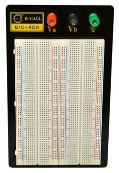
1. Breadboard 1660 (2×630 + 4×100)
Product code: MA4015
This 1660 breadboard is a great solution for prototyping electronics. You can reuse it several times for different projects and experiment with circuit designs.
Set of 3 x 4mm banana posts and 2 x 630 hole blocks with 4 x 100 hole bus strips. Mounted on a 215mm x 130mm metal plate with rubber feet.
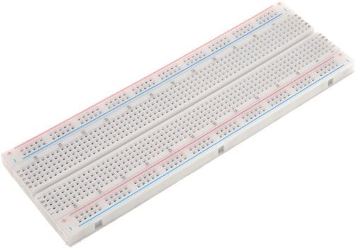
2. 830 Breadboard (630 + 2×100)
Product code: MA4009
Ideal for high frequency and low noise circuits. Interconnect any components with 20-29 AWG (0.3 – 0.8mm) wire. Special designed spring glip over 5,000 insertion cycles.
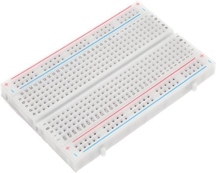
3. 400 Breadboard (300 + 2×50)
Product code: MA4004
Standard 0.1 inch spacings. Accepts all ICs, transistors, diodes, LEDs and passives. Uses solid hook up wire for interconnections. Boards keyed for easy expansion.
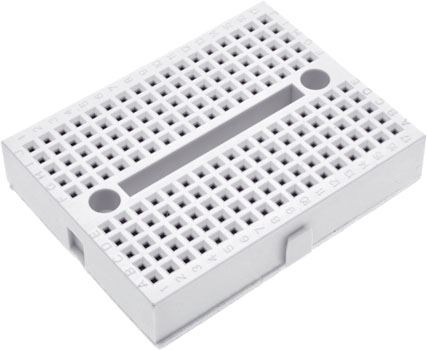
4. 170 Breadboard (2x5x17)
Product code: MA4000
Accepts a variety of wire sizes and is ideal for prototyping electronics. Completely reusable, featuring phosphor bronze nickel plated spring clips.
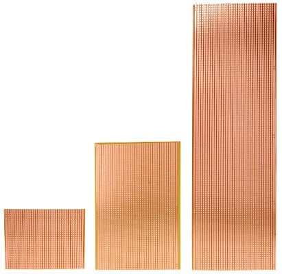
5. Prototyping Bread Boards & Strip Boards
Product code: MA354x
These are prototyping Vero-type breadboards and strip boards. Drilled with a 0.1” grid available in various lengths and 95mm wide.
You can prototype many electronics systems using strip boards. From small analogue or digital circuits through to complete CPUs!
The Bottom Line!
The purpose of breadboards is to make quick electrical connections between components. These include resistors, LEDs, capacitors and more. This allows you to test your circuit before permanently soldering it together.
For those new to electronics and circuits, breadboards are often the best place to start. They can house both the simplest circuit and complex ones.
It is a device that comes in handy, great for hobbyists and tinkerers to set up projects as a standalone device. Or even as a peripheral to an Arduino, Raspberry Pi, LaunchPad, and more development boards.
© Electrotech Brands Pty Ltd 2022
Write a Comment
You must be logged in to post a comment.