The Basics of Insulation Testers: A Handy Guide
June 7, 2022

There is so much to learn when it comes to testing equipment, and one topic of interest is insulation testers.
In our previous posts, we talked about the basics of various testing and measuring items. Today, we will share another instrument that every test technician should know.
Test equipment plays a major role in the productivity of a device. It is an essential element of electronics — insulation testers are no exception.
These tools come in a variety of sizes and output voltages, depending on the application. It can be tricky to know which one to use, let alone how to use it in the first place, if you are a beginner.
Luckily for you, this guide has everything you need to learn the basics of an insulation tester. Read on to learn more!
What Are Insulation Testers?
When an electric current is sent through a conducting wire, it would usually reach the destination pronto. But sometimes, current can be lost along the way.
This is where you need insulation testers, also known as “merger” or Megohmmeter. Insulation testing is vital to check if there is any leakage of current. Most importantly, if this discharge could be harmful.
An insulation tester determines the ‘insulation’ on various types of electrical equipment. This includes cables, transformers and switchgear.
It measures the total resistance between any two points separated by electrical insulation. With one, you will know how effective the dielectric (insulation) is in resisting the current flow.
Moreover, you can check if the equipment is in proper condition. While at the same time, detecting the service life of the insulation.
What problems could occur if there is an insulation failure?
- Electric shocks
- Burn injuries or fire accidents
- Plant operation
How Is the Insulation Test Done?
Your tester leads must be connected between one phase conductor and the ground. Choose the proper test voltage and duration for the testing.
Before disconnecting, discharge the test object through the ground. The actual insulation resistance could be high or low. Consider factors such as the temperature and moisture content of the insulation.
Other things to consider:
Check certain conditions before starting the insulation testing. Do a visual inspection to ensure surface dust and moisture have been removed from the component.
Moreover, isolate the component you will test from other connected systems. This includes the system ground and equipment like lightning-arrester, capacitor, and control transformer.
Measurement Procedure
Generally, an insulation resistance test has four phases: charge, dwell, measure, and discharge. During the charge phase, the voltage is ramped from zero to the selected voltage.
This provides stabilisation time and limits the inrush current to the DUT. Once the voltage reaches the selected value, it can then be allowed to dwell or hold before measurements begin.
And once the resistance has been measured, the DUT is discharged back to 0V during the final phase. Note: DUT stands for Device Under Test.
Further, insulation testers have four output connections to cover a variety of applications:
- Ground
- Shield
- (+)
- (-)
The output voltage is typically in the range of 50 to 1000 Volts DC.
When the voltage is applied, some current flows through the insulation. This current flow has three components:
- A “dielectric absorption” current
- Charging current
- Leakage current
Dielectric absorption
The insulation “absorbs” and retains an electrical charge slowly over time. To do this, apply a voltage to a capacitor for a long period, then quickly discharge it to zero voltage.
If the capacitor is left open for a long time, the meter will read a small voltage. And this residual voltage is caused by “dielectric absorption”. This occurrence is usually associated with electrolytic capacitors.
When you measure the IR of various plastic materials, this causes the IR value to increase over time. The inflated IR value is caused by the material absorbing charge gradually. And the absorbed charge looks like leakage.
Charging current
An insulated product exhibits the basic characteristics of a capacitor:
- Two conductors separated by a dielectric
- Voltage application across the insulation causes a current to flow
Depending on the capacitance, this current rises to a high value. This is especially true when the voltage quickly decays to zero as the product becomes fully charged.
Charging current decays to zero much more rapidly than the dielectric absorption current.
Leakage current
The steady-state current flows through the insulation. The leakage current equals the applied voltage divided by the insulation resistance. This test measures insulation resistance.
To calculate the IR value, apply the voltage and measure the steady-state leakage current. Do this after the dielectric absorption and charging currents have declined to zero.
Then, divide the voltage by the current. If the insulation resistance meets or exceeds the required value, the test is successful.
How Much Voltage Can Be Produced?
Insulation testers come in a variety of sizes and output voltages, depending on their application.
For one, a handheld 1000V Megohmmeter is usually sufficient for 600V class equipment. Meanwhile, larger sets for use on high voltage apparatus can output up to 15,000V or more.
Types of Insulation Testers
Commonly used methods for testing insulation resistance include:
- The Spot Reading test
- Time Resistance test
- Step Voltage test
Ideal for testing motor, generator, cable, and transformer insulation.
1. Spot reading test
Spot testing is suitable for a system with a small or negligible capacitance effect. A great example of this is a short wiring run.
A single Spot Reading test is of limited value. Even so, the results become significant when a series of tests are performed over time, and the results are compared. This is particularly true when all have the same test voltage and duration.
This comparison can help predict a potential insulation failure in time to take corrective action.
2. Time resistance test
A Time Resistance test, a.k.a. a dielectric absorption test, involves conducting a 10-minute test. For the first minute, measurements are taken every 10 seconds.
That is when absorption current will have the highest effect on resistance. After that, measurements are taken once per minute.
Since it provides significant results within a 10-minute duration, it is independent of temperature. It is also independent of the size of the system under test.
Time Resistance tests are used on large rotating electrical machinery, especially systems which:
- Have a high operating voltage
- Require high insulation resistance ranges
- Have a very constant test voltage
3. Step Voltage test
The Step Voltage test creates electrical stresses on internal insulation cracks. Plus, it identifies potential problems that may not be revealed by testing at lower voltages.
It involves testing at least two or more test voltages and comparing the results. The test begins at an initial test voltage.
At a specified interval, usually one minute, a measurement is recorded. Then, the test voltage is increased, usually five times the initial voltage. You can repeat this process through several steps.
It is also ideal for drying wet cables or equipment. Gradual voltage steps, applied for increasingly longer durations, can help dry through heating.
Get Your Insulation Resistance Tester Here!
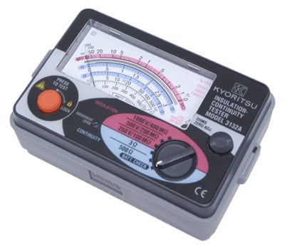
Here at Wiltronics, we offer a great range of Kyoritsu Electrical Test Equipment. One of them is the Kyoritsu Insulation Tester.

Kyoritsu Insulation Tester 3132A
Product code: ME3182A
Measure insulation and continuity with the Kyoritsu Insulation Tester 3132A. It features three insulation test ranges: (250/500/1000V).
Plus, with a live circuit warning buzzer and neon lamp to give you added safety. This unit is suitable for testing LV cables and installations and leakage between windings and motor frames.
You can also test single and 3-phase systems and equipment. It comes complete with leads.
The Bottom Line
Insulation testing is a crucial part of a resistance test to prevent damage and injury. It ensures the reliability of electrical systems and equipment.
Before performing any insulation test, be sure to observe safety measures. This includes extra guidelines that come with your test instrument.
© Electrotech Brands Pty Ltd 2022


Write a Comment
You must be logged in to post a comment.